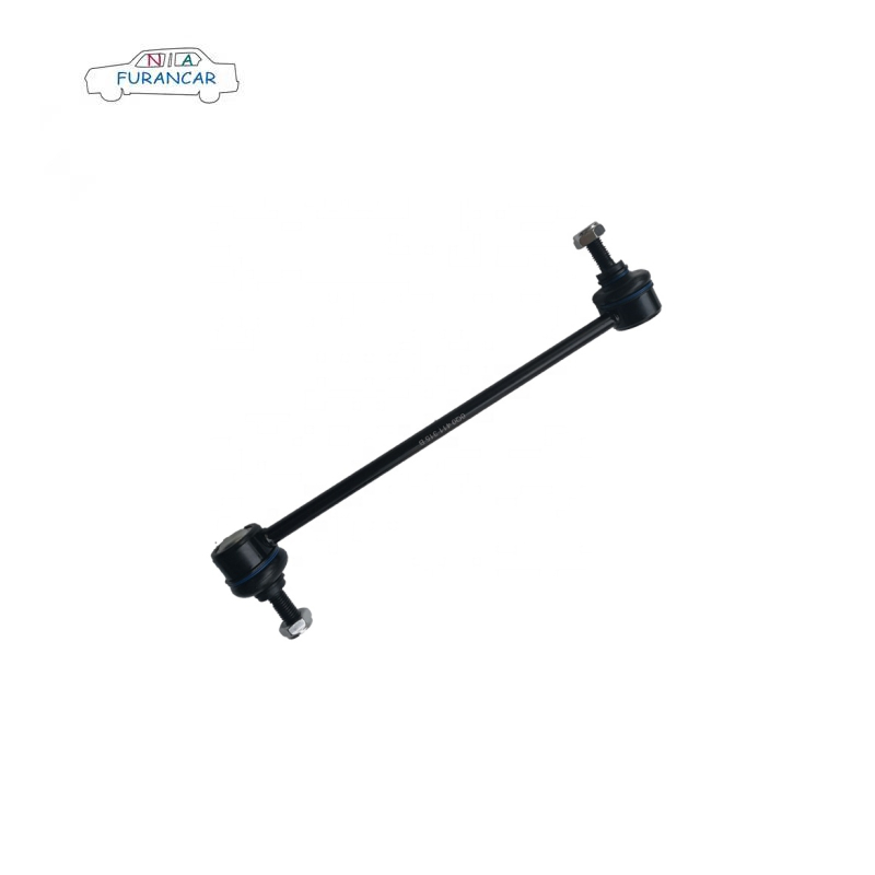
The role of Stabilizer Links

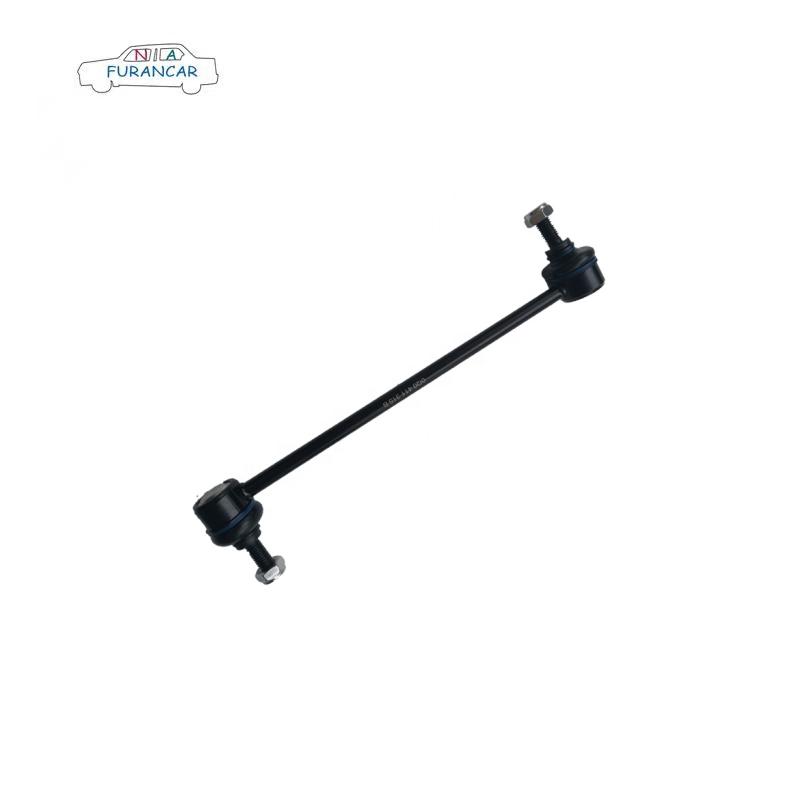
Stabilizer links act as components of auto suspensions, connecting several other parts that take much of the punishment as you pass over pot holes and other road imperfections.  
Function  
Modern cars use segmented suspensions. Stabilizer or sway bars have stabilizer links. The stabilizer bar holds pairs of wheels connected, while stabilizer links hook this larger piece with arms that go up to the wheels themselves. Ball joint connections enable turning and suspension travel.  

Significance  
Stabilizer bars links improve handling and shock absorption, keeping the car from swaying too much as you turn–which could lead to loss of control. Adding stabilizer links between the main bars and the wheels refines this process of control, so cars handle “tight.”  

Types  
With the prevalence of pot holes and bumpy roads, your entire suspension needs to withstand shocks, so stabilizer links employ cast iron, steel and alloy in their construction. Most have at least one ball joint for connecting with adjacent suspension components. A minority of stabilizer links lack ball joints altogether. Japanese and European car makers often employ this flat type.  

Identification  
You can identify stabilizer links by looking for ball jointed metal connections next to the wheels.Mechanics may refer to them simply as ball joints. Related but different parts of the suspension, such as idler and Pitman arms, can be found at the center of the undercarriage below your steering wheel. Most stabilizer links measure around 10 to 15 inches.  

Effects  
Worn stabilizer links affect steering, ride and fuel efficiency. Symptoms include a creaking or screeching noise as you pass road imperfections, plus wobble, skip and “dead zones” in steering. Don’t overlook these signs, as broken stabilizer links can lead to loss of control.  

Top 5 Reasons Lower Control Arm Bushings Are Noisy.

Top 5 Reasons Lower Control Arm Bushings Are Noisy.

People unfamiliar with cars may not understand what’s going on when they hear the strange jingle.

While there can be many reasons for unusual noise in a vehicle, a problem with the lower control arm bushing can be very noticeable.

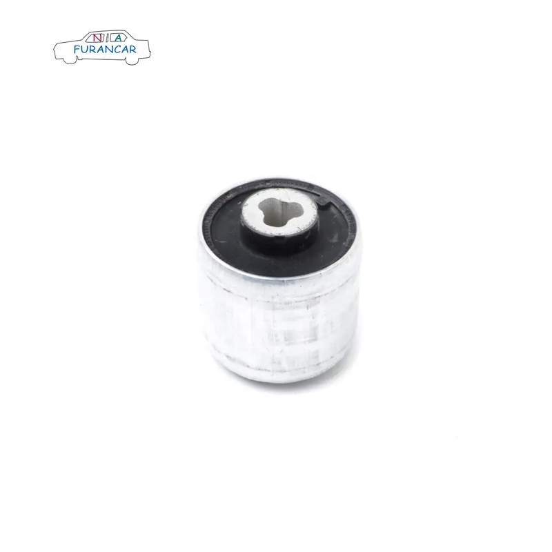
These noises are almost similar to knocks around the control arm area. Below are the five most common reasons for reducing control arm bushing noise.

  1. Bushing wear.

    Bushings don’t last forever. The more miles the vehicle travels, the more wear on the lower control arm bushings.

    You will start to hear a slight bump at first, but as bush wear increases, the bump will become louder and more consistent.
  2. The bushing is loose.

    If your lower control arm bushing is loose then it will be knocked between the metal parts surrounding it.

    This does not necessarily mean the bushing is worn.

    Maybe you’re driving over a loose bump.

    While working on another area of your vehicle, either that or the mechanic may have accidentally loosened.

    No matter what the cause, a loose bushing will always make the same knock.
  3. Damaged bushing.

    The lower control arm bushing may break due to excessive wear.

    It can also be accidentally damaged by a mechanic who is doing other work.

    A damaged control arm bushing produces a very loud ding, not a progressively louder than a worn bushing.
  4. Driving on uneven terrain.

    If you are driving over rough terrain, such as gravel or rocky roads, you will hear a knock or clang.

    Hearing will be amplified.

    Bushings in good condition will not loosen or rattle from driving on this terrain.

    However, if the bushing is not secured in place, the erratic movement of the vehicle over the terrain may loosen the bushing even more.
  5. Hard acceleration.

    If your bushing is loose, you will hear the loudest knock when you take off from a standstill.

    For example, when your vehicle is parked somewhere and you switch gears to drive and then press the gas pedal, the click will be loudest at this point.


What exactly is a turbocharger?

The engine generates power by burning fuel within the cylinders to perform work. As the amount of fuel input is constrained by the volume of air drawn into the cylinders, the engine's power output is consequently limited. Should the engine's operating performance already be at its optimum state, increasing output power can only be achieved by compressing more air into the cylinders to increase the fuel quantity, thereby enhancing the engine's capacity to perform work.


The turbocharger system is one of the most common forced induction systems in supercharged engines.

If, within the same unit of time, a greater volume of air-fuel mixture can be forcibly compressed within the cylinder (combustion chamber) for combustion (a small-displacement engine can “draw in” the same air volume as a large-displacement engine, thereby increasing volumetric efficiency), it can generate greater power output than a naturally aspirated engine at the same rotational speed. The principle is akin to directing an electric fan into the cylinder, forcibly pumping air into it to increase the volume and thereby achieve greater horsepower. The difference lies in the power source: instead of an electric motor, the fan is driven by the exhaust gases expelled from the engine.

Typically, engines incorporating such forced induction achieve at least a 30-40% power increase. This remarkable effect is precisely why turbochargers are so highly prized. Moreover, delivering optimal combustion efficiency and substantial power gains represent the core value a turbocharged system offers to a vehicle.

So how exactly does a turbocharger function?


First, the exhaust gases expelled from the engine drive the turbine impeller at the exhaust end (right side in the diagram above), causing it to rotate. This rotation in turn drives the connected compressor impeller on the opposite side (left side). The compressor impeller then forcibly draws air through the inlet. This air is compressed by the rotating blades before entering progressively narrower compression passages for secondary compression. The temperature of this compressed air exceeds that of the intake air, necessitating cooling via an intercooler before injection into the combustion chambers. This cyclical process constitutes the operating principle of the turbocharger.


The function of the throttle valve


Within the engine's intake system, there are two principal components: firstly, the air filter, which is responsible for filtering impurities from the air; and secondly, the intake manifold, which directs the air into the cylinders. Within the intake manifold lies a crucial component known as the throttle valve.

The throttle valve's primary function is to regulate the volume of air-fuel mixture entering the cylinders. When driving, the depth to which we depress the accelerator pedal directly controls the throttle valve's opening. The deeper the pedal is pressed, the wider the throttle valve opens, allowing greater air-fuel mixture intake and consequently increasing the engine's rotational speed.


Traditional cable-operated throttles utilise a steel cable connected at one end to the accelerator pedal and at the other to the throttle valve, employing a 1:1 transmission ratio. This method yields less than ideal control precision. In contrast, modern electronic throttle systems employ position sensors to transmit data such as the force and amplitude of the accelerator pedal depression to the control unit for analysis. This process interprets the driver's intent, after which the ECU calculates the actual throttle opening required and issues commands to operate the throttle motor, thereby achieving precise throttle control.


Is the intake manifold length variable?


A control valve installed within the intake manifold can divide it into two sections by opening and closing, thereby altering its effective length. This adjustment of the intake manifold's length primarily serves to enhance the engine's intake efficiency across varying rotational speeds, thereby improving power delivery performance throughout the entire rev range.

Why does the exhaust manifold have such an odd shape?


The vehicle's exhaust system primarily comprises the exhaust manifold, three-way catalytic converter, silencer and exhaust pipes. Its principal function is to expel the combustion exhaust gases from the cylinders into the atmosphere.


The exhaust manifolds we commonly observe feature rather peculiar shapes. This design serves to minimise interference between exhaust gases from different cylinders or the occurrence of backflow, thereby preventing any detrimental impact on the engine's power output.


How does a turbocharger boost pressure?


Turbocharging is commonly abbreviated as Turbo or T. When we see markings such as 1.4T or 2.0T on a vehicle's rear, it indicates that the engine is turbocharged.


The turbocharger primarily consists of two components: the turbine and the compressor, connected by a drive shaft. The turbine's inlet is linked to the engine's exhaust manifold, while its outlet connects to the exhaust pipe. The compressor's inlet is connected to the intake manifold, and its outlet is connected to the intake manifold. The exhaust gases expelled from the engine strike the turbine, causing it to spin at high speed. This, in turn, drives the coaxial compressor to rotate rapidly, forcibly delivering pressurised air into the cylinders.


Turbocharging primarily harnesses the energy from engine exhaust gases to drive a compressor, thereby boosting the intake air pressure. This process consumes virtually no engine power, delivering excellent sustained acceleration. However, at low speeds, the turbocharger cannot engage promptly, resulting in a certain degree of lag.


What about mechanical supercharging?


Mechanical supercharging primarily involves using the crankshaft's power to drive a mechanical air compressor, thereby compressing air. However, this process incurs a certain degree of power loss from the engine during operation.


As the mechanical supercharger is directly driven by the crankshaft, it commences operation whenever the engine is running. Consequently, the engine delivers impressive torque output even at low revs. However, during high-speed operation, the mechanical supercharger imposes significant power losses on the engine, resulting in less pronounced power gains.


How does a twin-turbocharged engine work?


A twin-charged engine, as the name suggests, refers to an engine equipped with two superchargers. Should an engine utilise two turbochargers, it is termed a twin-turbocharged engine.


To address turbocharger lag in exhaust gas-driven systems, two identical turbines are connected in parallel on the exhaust manifold. At low engine speeds, the reduced exhaust flow can drive the turbines to high rotational speeds, generating sufficient boost pressure and thereby minimising turbo lag.

As previously noted, turbochargers exhibit lag at low engine speeds, yet deliver substantial boost at high speeds, markedly enhancing engine power without consuming significant engine power. In contrast, mechanical superchargers are directly driven by the engine's rotation, eliminating turbocharger lag but incurring some power loss and offering lower boost levels. Combining these two systems allows their respective advantages to complement each other.

As with the 1.4-litre TSI engine fitted to the Volkswagen Golf GT, the designers combined a turbocharger with a supercharger. The supercharger is mounted on the engine's intake system, while the turbocharger is positioned on the exhaust system. This arrangement ensures effective boost delivery across the entire engine speed range, from low to high revs.


Working Principle of a Turbocharger


The operating principle of a turbocharger is actually quite straightforward. Simply put, it harnesses the exhaust gases emitted by the engine to drive the turbine. This turbine, in turn, drives a fan connected to the same shaft, continuously forcing fresh air into the engine cylinders. Consequently, more air enters the cylinders per unit time, thereby enhancing the engine's efficiency.


Turbochargers are high-temperature components, as the gases driving their operation are drawn directly from exhaust gases expelled from the cylinders, reaching temperatures of 900°C to 1000°C. Under full load conditions, the turbine's rotational speed can attain 180,000 to 200,000 revolutions per minute. Operating at such extreme temperatures and rotational speeds necessitates exceptionally efficient and stable lubrication. Moreover, functioning within high-temperature and high-pressure conditions demands that all turbocharger components and lubricants exhibit excellent heat resistance and sealing properties. Consequently, maintenance should focus on the following aspects:


1.Selection of engine oil

Many motorists find themselves at a loss when selecting engine oil for replacement. Damage to turbochargers typically stems from compromised oil seals between the unit and intake manifold, resulting in significant oil consumption. Professional investigations reveal that a significant proportion of oil seal failures stem from owners failing to change their engine oil at the recommended intervals, or using substandard oil. This prevents the floating turbocharger main drive shaft from receiving adequate lubrication and heat dissipation, causing the oil seal to deteriorate under high temperatures and resulting in oil leakage.


It is therefore recommended that turbocharged engines should be fitted with high-quality engine oil that offers excellent high-temperature resistance and oxidation stability, whilst also ensuring that the oil change interval is appropriately shortened.


2.Ensure the turbine remains clean

The clearance between the turbocharger shaft and its bearing sleeve is extremely small. Consequently, if contaminated engine oil is used, or if impurities enter due to a dirty oil filter, this will cause excessive wear on the turbocharger. Furthermore, should the intake air contain significant impurities, these dust particles entering the high-speed turbine impeller will collide with it. This results in unstable turbine operation and accelerated wear of the bearing bushings and seals. Consequently, vehicles equipped with turbochargers must pay particular attention to promptly replacing both the oil filter and air filter to maintain the cleanliness of the turbocharger.


3.Cold starts should be gradual; allow the engine to idle for a moment after warming up before switching it off.


During the initial stages of a cold start, engine oil is typically at a low temperature and exhibits greater viscosity, resulting in suboptimal lubrication. Reaching normal operating temperature requires a gradual process and time. Forcing the turbocharger to operate at full load within these first few minutes will increase wear and tear, thereby shortening its lifespan.

The correct approach is as follows: during the first few minutes of driving, maintain a slow speed for several minutes to allow the oil to reach its optimal state before accelerating to high engine speeds. This is particularly crucial in northern winters, where it is essential to let the vehicle warm up after a cold start before proceeding. This benefits both the vehicle and the driver.

When parking, as the turbo operates at extremely high temperatures, it is advisable to idle the engine for a short while before switching it off. At this stage, the engine's oil and cooling systems remain active, allowing the turbo's temperature to gradually decrease. Note that after switching off the engine, the turbo will continue to spin due to inertia, and it still requires oil lubrication. If you abruptly switch off the engine, the entire engine system ceases operation, abruptly halting both the turbocharger's cooling system and oil supply. It would then rely solely on natural cooling, which can drastically reduce the turbocharger's lifespan.

4.Regular inspections are important


Much like regular health check-ups for the human body, cultivating this good habit helps us detect turbocharger faults promptly and prevent problems before they arise. For instance: inspect the turbocharger's exterior for damaged sealing rings; check oil inlet and return pipe connections for looseness or leakage; examine the exhaust outlet for residual oil; verify the compressor inlet duct walls are free of oil; and listen for unusual noises or abnormal vibrations. Should any of these irregularities be detected during routine operation, prompt professional servicing is essential to prevent more severe component damage.

What Is Power Steering Hose Replacement?

What Is Power Steering Hose Replacement?
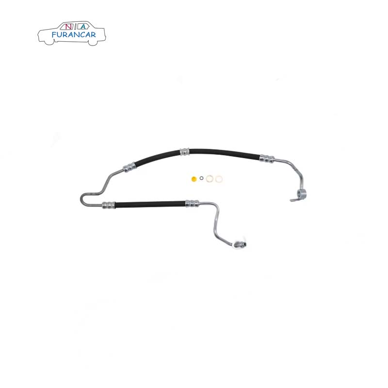
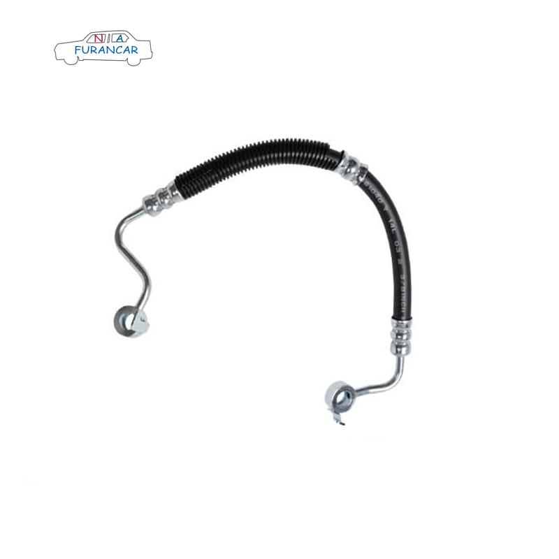
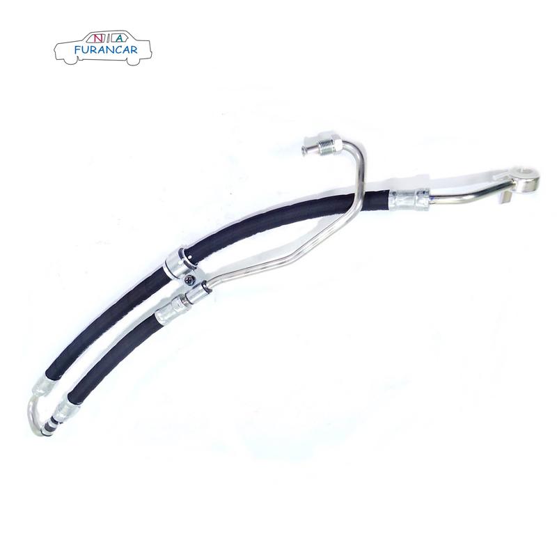
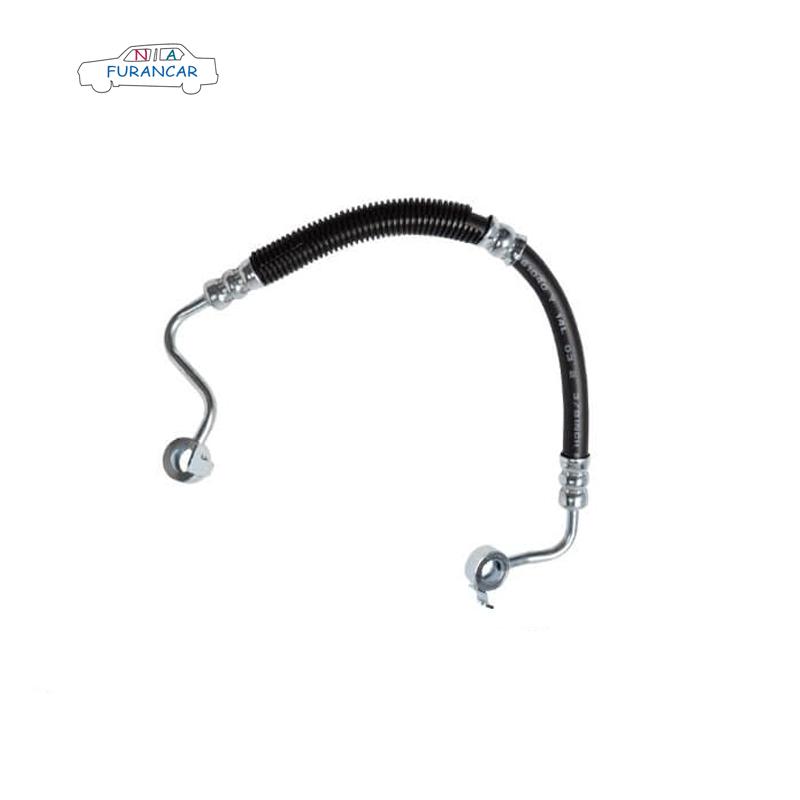
The power steering hoses and the connecting components can be located in a number of places. They may be under the axle, while the gearboxes could be near the wheel well or somewhere along the frames. The difference in location may not make the replacement process much longer or more involved for the mechanic, but the mechanic will likely look up manufacturer’s specifications for the vehicle before attempting work on the hoses to ensure they are dealing with the right components. They want to be sure they know where to look for the problem and not end up messing with the wrong components.

This process should be fairly quick, taking less than two hours and not involving more than a few parts at most. However, if you drive your vehicle in a damaged state, then more damage is likely to occur.

Benefits of Power Steering Hose Replacement
Since the hoses supply fluid to the power steering system, you need them if you are going to have an easy time driving the car. You will have better control over the wheel and the car itself with these hoses replaced, if they were giving you trouble before. You will also prevent damage to other systems that could have accrued if the problem was allowed to persist.
What Is Done during Power Steering Hose Replacement?
The mechanic will find out where the hoses are located, first of all, and check for leaks or other problems to ensure the issue is localized and that the hoses are all that needs to be changed out.

WHY DOES MY SWAY BAR LINK BREAK?

To figure out why your sway bar link breaks, it's first important to understand how sway bars work. The sway bar, also known as an anti-roll bar or stabilizer bar, is a vital part of your vehicle’s suspension system and keeps it level during cornering. Sway bars are usually a long and hollow arched steel bar attached to the chassis, connecting the left and right sides. This stabilizes your vehicle while still allowing the suspension to move on its own.

Sway bar links are what connect the outer end of the sway bar to the suspension component. Because the sway bar itself is a torsional swing, the sway bar link smooths the motion transfer between the sway bar and the control arm. The sway bar link maintains the camber angle of the inner wheels to control motion.

Like many automotive parts, over time the sway bar links will wear out. Water intrusion that leads to rust, age, and lack of lubrication all contribute to deterioration over time. A knocking noise from your suspension, rattling sounds while taking corners and hitting bumps, and excessive body roll are signs it may be time for a replacement. Sway bars and their components are all paramount to driver safety.

Everything you need to know about HOWO telescopic aerial work platform truck

▲ What is the HOWO telescopic aerial work platform truck?


The HOWO telescopic aerial work platform truck, also known as HOWO truck mounted aerial work platform, HOWO bucket lift  truck, HOWO manlift truck, is a special engineering vehicle based on the HOWO 4×2 light truck chassis and equipped with a telescopic boom aerial work platform. It is mainly used for high-altitude operations such as construction, advertising installation, power line maintenance, and garden trimming.


HOWO 33m aerial work platform truck


▲ HOWO manlift truck structure:

The HOWO telescopic boom manlift truck mainly consists of a chassis, a slewing mechanism, a lifting mechanism, a working platform, outriggers, and a control system. The specific structure is shown in the figure below:


HOWO telescopic aerial work platform truck drawing


▲ Features of HOWO Telescopic Bucket Lift Truck:

1. 7-section boom with 6 sections synchronously telescoping. Adopts 16-sided high-strength steel, offering high strength and light weight.

2. Maximum working height: 33m; Maximum working radius: 18m; Platform rated load: 200kg.

3. Front V-shape and rear V-shape hydraulic outriggers with a longitudinal span of 5800mm and a lateral span of 6100mm. Individually adjustable for strong stability.

4. CAN bus electronic control system equipped with a wireless remote controller with an effective range of approximately 100 meters.

5. Equipped with safety devices such as an emergency power source, bi-directional hydraulic balance valves, and outrigger soft leg protection.

HOWO 33m bucket lift truck

Chassis

HOWO 4×2

Engine

YN4102, 116HP, diesel engine

Max. working height

33 meters

Max. working radius

18 meters

Bucket size

1800×700×1100 mm

Rated load of bucket

200 kg

Rotation angle

360°

Outriggers

X-type, 4 pieces, individually adjustable


▲ HOWO truck mounted aerial platform technical drawing:


HOWO 33m bucket lift truck drawing


▲ HOWO aerial work bucket truck application areas:

● Municipal Engineering: Streetlights, traffic facilities, surveillance camera installation and maintenance

● Power and Telecommunications: Line erection, base station antenna maintenance

● Building Construction: Exterior wall installation, curtain wall maintenance, aerial equipment installation

● Landscaping and Sanitation: Tree pruning, high-rise property cleaning and maintenance

● Transportation and Bridges: Overpass and tunnel facility maintenance

● Advertising Venues: Billboard and stadium aerial equipment installation and maintenance

HOWO 33m man lifter truck HOWO 33m man lifter truck


Take a look at HOWO aerial lift bucket trucks that may be of interest to you:

HOWO Straight Aerial Platform Truck Safety Monitoring System introduction

HOWO 154HP Truck Mounted Aerial Work Platform

50ton Boom Rotator Integrated Wrecker Tow Truck DONGFENG

Integrated towing wrecker truck is a special operation vehicle that integrates towing, lifting and wrecking functions, and 50ton Boom Rotator Integrated Wrecker Tow Truck DONGFENG is specially designed to quickly handle road accidents or broken vehicles. Combined wrecker truck is also called wrecker towing truck, flatbed tow truck, tow truck hydraulic, tow trucks wreckers, rotator tow truck, towing wrecker truck, road wrecker truck, wrecker truck towing truck, road wrecker, rotator wrecker, recovery wrecker, wrecker tow truck, recovery truck, rotator recovery truck, wrecker with crane, etc.

1. Main Function: Integrated wrecker truck equipped with lifting winch device and wheel bracket which can lift, towing, back load and transport.
2. Application: Widely used in road, airports, docks, auto repair company, industry and highway departments, timely,  fast clean-up accident, failure, illegal and other vehicles.

DONGFENG integrated wrecker tow truck


Dongfeng integrated rotator tow wrecker truck

Heavy duty combined wrecker tow truck is equipped with a sturdy chassis and a capacity of 30 to 50 tons, this truck combines power with precision to tackle diverse terrains with ease. Its hydraulic tipping mechanism ensures quick and accurate unloading of materials, enhancing productivity on construction sites. With a focus on driver comfort and safety, the truck's interior features ergonomic design elements and advanced control systems.Integrated tow wrecker truck

50ton Boom Rotator Integrated Wrecker Tow Truck DONGFENG Truck Specification
Chassis model  CEEC5310TQZ
Cab DONGFENG cab, with power steering. Electronic flameout,left hand drive
Driving Type  8x4 left hand drive
Max Speed (km/h) 95
Overall dimension(mm) 11120×2500×3695
Mass in working order( kg) 22000
GVW( kg) 31000
Tank Capacity (L) 400
Wheelbase(mm) 1850+4600+1350
F/R track base (mm) 2022/1830
F/R overhang (mm) 1500/1000
Approach/Departure Angel  14/18
Tire  12.00R20
Clutch  Single-plate dry diaphragm spring clutch φ430
Steering  Hydraulic steering with power assistance 
Gear box Manual Synchromesh
FAST, 12 SPEED FORWARD + 2 REVERSE
Bridge Front axle 6.5+6.5 Tons
Rear axle 16+16 Tons
Enging Model WP12.420E32
Horse power 420HP
Displacement 11976L
Braking  system Service Brake  Compressed air brake 
Park Brake  Spring energy 
Eletric system  24v
Integrated Combined Rotator Truck Upper-Body specification
Hydraulic Under Lift at Rear
Fully Retracted Lifting weight(kg) 50000
Fully Extend Lifting Weight(kg) 15000
Max. Rated towing weight(kg) 60000
Max effective length of boom(mm) 1460-3599
Extension traveling of boom     (mm) 1639
Boom structure
Maximum lifting height(mm) 6500
Fully Retracted Lifting weight(kg) 25000
Fully Extended Lifting weight(kg) 8000
Extension traveling of hoisting boom(mm) 3300
Hydraulic winches & steel cables
Type: Planetary type
Quantity (set) 2
Max. Pulling power of winch(kN) 100
Length of steel cable(m) 60
Speed of winch (m/min) 5
Diameter of winch(cm) 0.22
Hydraulic Outriggers
Quantity 2
type in-built with power elevation &extension 
Power take off 
Type  PTO drive from transmission
Wrecker Operation
Description  Panel board comprising joysticks and hydraulic meters installed in a suitable place out of crew cabin.
Hydraulic System
Description uitable capacity gear pumps for boom movement, telescoping cylinder, power steering and control valves & control system shall be with adequate size oil reservoir, integral oil cooler, valves etc.
Safety Device 
Auto brake  for winch  Automatic safe brake in case winch / Engine fail.
Hydraulic valves  Necessary hydraulic pressure relief & lock valve/ valves

Dongfeng integrated rotator tow wrecker truck

Working parameter for combined rotator truck


DONGFENG 12 wheeler combined rotator wrecker tow truck is a special rescue vehicle that integrates towing, lifting and towing functions. It is mainly used to quickly handle road traffic accidents or faulty vehicles. Its core feature is that the functions of the towing truck and the crane are integrated into the same vehicle body, and the linkage operation is realized through a hydraulic or electronic control system. DONGFENG integrated wrecker tow truck can not only tow the faulty vehicle away from the scene, but also use the boom to lift obstacles or accident vehicles. This integrated design greatly improves the rescue efficiency, especially suitable for key scenes such as highways and urban main roads that require rapid dredging, and can cope with the complex rescue needs of cars, trucks and even small engineering machinery.

Dongfeng integrated rotator tow wrecker truck


From a structural point of view, the heavy duty 8x4 rotator tow truck is usually equipped with key components such as hydraulic telescopic boom, winch towing device, adjustable flat plate and stabilizing legs. The boom can rotate 360° and flexibly adjust the angle, and cooperate with the winch or flat plate to achieve vehicle towing, loading or direct lifting; the stabilizing legs are deployed during operation to enhance vehicle stability and avoid rollover risks. According to the mission requirements, common types are divided into flatbed towing integrated type (towed vehicles by tilting the flatbed) and heavy-duty rotating boom type (suitable for large-tonnage rescue), with a carrying capacity ranging from 3 tons to more than 80 tons, meeting different rescue scenarios.

Dongfeng integrated rotator tow wrecker truck


The advantages of this model heavy duty 50tons integrated wrecker tow truck are versatility, efficiency and safety. A single dispatch can complete tasks such as towing, lifting, and towing, reducing equipment scheduling time, and is particularly suitable for complex situations such as cleaning scattered goods and resetting overturned vehicles in traffic accidents. At the same time, its warning lighting system and professional operating specifications (such as operating with a special driving license and strict load restrictions) ensure the safety of the rescue process. As an important equipment of the modern traffic emergency system, the towing and towing combined tow truck plays an irreplaceable role in improving road traffic efficiency and reducing the risk of secondary accidents.

Dongfeng integrated rotator tow wrecker truck


Moldova clients customize Isuzu double row Aluminum Alloy dropside body truck

POWERSTAR Aluminum alloy drop side cargo truck ISUZU refers to a logistic vehicle whose main structural components is aluminum alloy materials, especially the drop side cargo and safety fence. But as for cargo body frame and floor are made of high strength carbon steel materials, all with electrophoretic painting, which can guarantee long life service and same time guarantee loading capacity. The core goal of ISUZU aluminium dropside truck is to use the characteristics of aluminum alloy to achieve lightweight vehicles, thereby to carry more weight cargo. Also the customized Isuzu dropside trucks are double cabin row, which means truck can carry totally 5 people for convenient working.


Isuzu dropside cargo truck with Customized Double Cabin Row:

ISUZU double cabin drop side truck is modify based on classical ISUZU new NPR truck chassis, equipped with double cabin row supports seating for five people, with thickly padded seats that reduce fatigue during long drives; abundant storage space both in first and second row, all makes it convenient to storage. Isuzu aluminium dropside body equipped with 4KH1CN6LB diesel engine, 88KW / 120HP horsepower and 2999cc emission, meet international EURO 6 emission standard. Also can be customized to remove the DPF and ADBlue to make truck workign as EURO 4 or 5. Japanese ISUZU technology MSB gearbox equipped with 5 forward and 1 reverse, manual operation to make truck driving more smoothly. 7.00R16 tires with single in the front axle and double at the rear axle, also including one spare tire for emergency. 

Isuzu double cabin dropside cargo truck


Isuzu double cabin aluminum dropside cargo truck


Isuzu cargo lorry truck with Aluminum alloy dropside body:
Moldova customer request that the dropside body mounted on ISUZU NPR double cabin chassis should be light and strong, able to withstand high intensity impacts and work well in harsh environment. Normally the Aluminum alloy dropside body is lighter than the steel body, usually the density of aluminum alloy is about 1/3 of that of steel, this is the basis for lightweighting. The use of special aluminum dropside body is never rust and long lifer service. 

Aluminum alloy cargo boxes is the most widely used part for dropside truck, including Aluminum side panels, floor panels, roof panels, door panels, etc. This is the core advantage. Compared with steel trucks of the same specifications, the weight of aluminum alloy trucks can usually be reduced by 20%-30% or even more.

Isuzu double row dropside cargo truck


Under the total mass limit, the lighter the vehicle curb weight, the more cargo it can legally load. This means that more cargo can be transported in a single trip, improving transportation efficiency. This is crucial for transportation scenarios that charge by weight or pursue maximum benefits per trip. Since the vehicle curb weight is reduced, the engine load is reduced, which directly leads to reduced fuel consumption and lower operating costs. The reduction in fuel consumption is usually proportional to the weight reduction ratio.

Isuzu aluminum alloy dropside cargo dtruck


Aluminum alloy dropside truck ISUZU is logistics vehicles that use aluminum alloy materials dropside cargo body to replace traditional steel with the core goal of achieving vehicle lightweighting. Its most prominent advantage is lower curb weight, thereby bringing core benefits such as increased effective load, reduced fuel consumption, reduced emissions, and good corrosion resistance. It is one of the important models for the development of modern logistics towards high efficiency, energy saving, and environmental protection.


Isuzu dropside body lorry truck with Aluminum alloy body advanced features as below:

Body part are Aluminum Alloy and Steel for strength

Stonger ISUZU chassis mounted dropside body, super steel for frame with electrophoretic painting antirust, with Aluminum alloyd fence and dropside

Isuzu dropside cargo truck with aluminum alloy drop side body


Body part building with riverts and bolts

Stonger Aluminum alloy dropside cargo body with all parts connected with rivets and screws, with small amount of welding and easy for installation and maintenance.

Isuzu dropside cargo truck with aluminum alloy drop side body


Dropside Body with strength skateboard floor

Dropside body mounted with skateboard floor, and each side with 3 sets aluminum hook for belt fasten

Isuzu dropside cargo truck with aluminum dropside body


Dropside Body with Aluminum fence

Dropside body mounted with aluminum alloy dropside fence, also two sides safety fence, which can efficiently avoid rust and reduce curb weight

Isuzu dropside truck with aluminum fence


Isuzu cargo truck body

Dropside cargo truck body mounted with skateboard floor, optional as anti-skip FRR honeycomb floor or Non-slip fiberglass honeycomb panel

Isuzu cargo truck body


Isuzu cargo truck body with safety lock

Dropside cargo truck body mounted with Aluminum alloy safety lock, which is hidden type, more safety and convenient

Isuzu dropside cargo truck body with lock


Use And Maintenance of Loader Machinery During The Running-in Period

The running-in period is an important link to ensure the normal operation of the small wheel loader, reduce the failure rate and extend its service life. However, at present, some users ignore the special technical requirements of the running-in period of the new machine due to lack of common sense of loader use or because of tight construction period or want to get benefits as soon as possible. Some users even think that the manufacturer has a warranty period anyway, and the manufacturer is responsible for repairing the machine if it breaks down. Therefore, the machine is overloaded for a long time during the running-in period, resulting in frequent early failures of the machine, which not only affects the normal use of the machine and shortens the service life of the machine, but also affects the progress of the project due to machine damage. Therefore, the applicability and maintenance of the loader running-in period should be given full attention.
1. Characteristics of the running-in period
1. Fast wear rate
Due to the influence of factors such as the processing, assembly and adjustment of new machine parts, its friction surface is rough, the contact area of the mating surface is small, and the surface pressure is uneven. During the operation of the machine, the concave and convex parts of the surface of the parts are embedded and rubbed against each other, and the metal debris worn off continues to participate in the friction as abrasive, which accelerates the wear of the mating surface of the parts. Therefore, it is easy to cause wear of parts (especially mating surfaces) during the running-in period, and the wear rate is fast. At this time, if the operation is overloaded, it may cause damage to parts and cause early failures.
2. Poor lubrication
Due to the small fit clearance of newly assembled parts, and due to assembly and other reasons, it is difficult to ensure the uniformity of the fit clearance, and it is not easy for lubricating oil (grease) to form a uniform oil film on the friction surface to prevent wear. This reduces the lubrication efficiency and causes early abnormal wear of the machine. In severe cases, it will cause scratches or bites on the precision-matched friction surface, leading to the occurrence of failures.
3. Looseness
Newly processed and assembled parts have deviations in geometric shape and fit size. In the early stage of use, due to alternating loads such as impact and vibration, as well as factors such as heat and deformation, coupled with excessive wear and other reasons, it is easy for the originally tightened parts to loosen.
4. Leakage occurs
Due to the looseness of parts, vibration and heat of the machine, the sealing surface of the machine and the pipe joints will leak. Some casting and processing defects are difficult to find during assembly and debugging, but due to the vibration and impact during the operation, this defect is exposed, manifested as oil (water) leakage. Therefore, leakage is prone to occur during the running-in period.
5. Many operating errors
Due to insufficient understanding of the structure and performance of the machine (especially new operators), it is easy to cause failures due to operating errors, and even cause mechanical accidents.
2. Applicability and maintenance during the running-in period
1. Since construction machinery is a special vehicle, operators should receive training and guidance from the manufacturer, have a full understanding of the structure and performance of the machine, and gain certain operating and maintenance experience before operating the machine. The "Product Use and Maintenance Manual" provided by the manufacturer is a necessary document for operators to operate the equipment. Before operating the machine, be sure to read the "Use and Maintenance Manual" first and perform operation and maintenance as required.
2. Pay attention to the workload during the running-in period. Half of the workload during the running-in period should not exceed 60% of the rated workload, and arrange a suitable workload to prevent overheating caused by long-term continuous operation of the machine.
3. Pay attention to regularly observe the indications of each instrument. If any abnormality occurs, stop the machine in time to eliminate it. Stop the operation before the cause is found and the fault is eliminated.
4. Pay attention to regularly check the level and quality of lubricating oil, hydraulic oil, coolant, brake fluid and fuel oil (water), and pay attention to checking the sealing of the whole machine. If the inspection finds that there is too much oil and water, the cause should be analyzed. At the same time, the lubrication of each lubrication point should be strengthened. It is recommended that grease should be added to the lubrication points every shift during the running-in period (except for special requirements).
5. Keep the machine clean, adjust and tighten loose parts in time to prevent loose parts from aggravating the wear of parts or causing parts to be lost
6. At the end of the running-in period, the machine should be subject to mandatory maintenance, inspection and adjustment, and pay attention to the replacement of oil.
In short, the requirements for the use and maintenance of wheel loader machine, during the running-in period can be summarized as: strengthen training, reduce load, pay attention to inspection, and strengthen lubrication. As long as you pay attention to and implement the maintenance and maintenance of the loader during the running-in period as required, you will reduce the occurrence of early failures, extend the service life, improve operating efficiency, and make the machine bring you more benefits.

High Pressure Water Sprayer Backpack

tint sprayer backpack

High Pressure Water Sprayer Backpack 3L/6L

Design:Water Pump High Pressure Sprayer Design With Smart Battery Pack, Portable Remote System.  Ultra Flexible Hose with 200 Micron Filter and Adjustable Brass Nozzle.

Water Bladders Capacity: 3L /6L
Battery capacity: 3000mah
Hose: 1.2 metres, Durable Ultra Flexible Hose
Applications:  Car wrap film, gardening work, high-altitude operation,outdoor
LOGO:Customize

High Pressure Water Sprayer Backpack plays an important role in car wraps film.

It can be used to spray detergent and water to help clean the car surface and remove impurities such as dust, dirt and grease to ensure that the surface before applying the film is clean and smooth. High-pressure water sprayers can provide sufficient pressure and spray force to ensure that the cleaning agent can fully penetrate and clean the car surface.

In addition, the High Pressure Water Sprayer Backpack can also be used to spray the lubricant required when applying the film, helping the film material to slide and adjust its position more easily, thereby ensuring the smoothness and adhesion of the film. Spraying lubricant can reduce friction and bubble generation during the film application process, and improve the quality and efficiency of film application.

Therefore, the High Pressure Water Sprayer Backpack can clean the surface and spray lubricant during the car wrapping process, helping to ensure the smooth progress of the wrapping process and improving the wrapping effect.


High Pressure Water Sprayer Backpack has many uses in life,

including but not limited to the following aspects:

1. Gardening and Agriculture: Used to spray water, fertilizers, pesticides and herbicides to help plants grow and protect crops.


2. Cleaning and disinfection: used for cleaning vehicles, buildings, yards, roads and other surfaces, as well as for disinfection and sterilization.

3. Firefighting and emergency rescue: Can be used to extinguish fires or provide emergency rescue during outdoor activities, camping or emergency situations.

4. Car wash: Used for home or commercial car wash services, providing high-pressure water flow to clean car surfaces.

5. Construction and decoration: used for cleaning construction sites, spraying paint, cleaning walls and floors, etc.

6. Household Cleaning: Used for cleaning garden furniture, patios, driveways, railings and other outdoor areas.

7. Water sports: used for washing boats, kayaks, surfboards and other water sports equipment.

Overall, the High Pressure Water Sprayer Backpack is useful in many daily life and work scenarios, providing a convenient and efficient cleaning and spraying solution.