A Brief Discussion on the Technical Development of Automotive Air Conditioning Hose Assemblies

The automotive market is becoming increasingly competitive, with the air conditioning system representing a crucial component of the vehicle. Within this system, the piping network constitutes an indispensable element of its development, serving to facilitate the circulation between the blower and compressor, as well as between the evaporator and engine. This article primarily outlines the development process of automotive air conditioning piping.

The air conditioning system constitutes a vital component within a motor vehicle, primarily serving to provide a comfortable cabin environment by delivering warm air during winter months and cool air during summer. Typically, a vehicle's air conditioning system comprises a compressor, an electronically controlled clutch, a condenser, a blower fan, a receiver-drier, refrigerant piping, an evaporator, an expansion valve, and refrigerant. In new energy vehicles, it may additionally incorporate critical components such as a battery cooler, whose principal function is to dissipate heat from the battery pack. The air conditioning compressor serves as the system's ‘heart’, elevating the refrigerant pressure within the piping to facilitate its liquefaction and heat dissipation within the condenser, whilst also circulating the refrigerant throughout the system. The refrigerant's circulation within the system continuously absorbs heat from the cabin air, achieving cooling within the vehicle. Each refrigerant cycle comprises four processes: compression, condensation, throttling, and evaporation, as illustrated in Figure 1. Heating in the air conditioning system is primarily achieved through engine heat (in petrol vehicles) or a PTC thermistor-type heating system.

Air conditioning refrigerants serve as the working medium within the refrigeration cycle, achieving cooling through phase changes that facilitate heat exchange. With heightened environmental awareness, our company currently employs two primary refrigerants: R134a and R1234YF. R1234YF is an automotive air conditioning refrigerant that exhibits zero ozone depletion potential and a low global warming potential (GWP). It complies with EU automotive air conditioning regulations and is typically utilised in vehicle models exported to the European Union. However, R1234YF carries a higher cost and is classified as a hazardous and explosive substance.

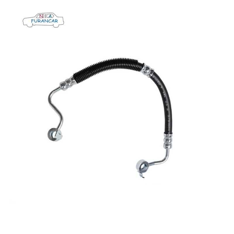
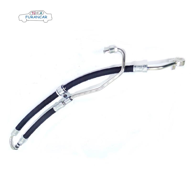
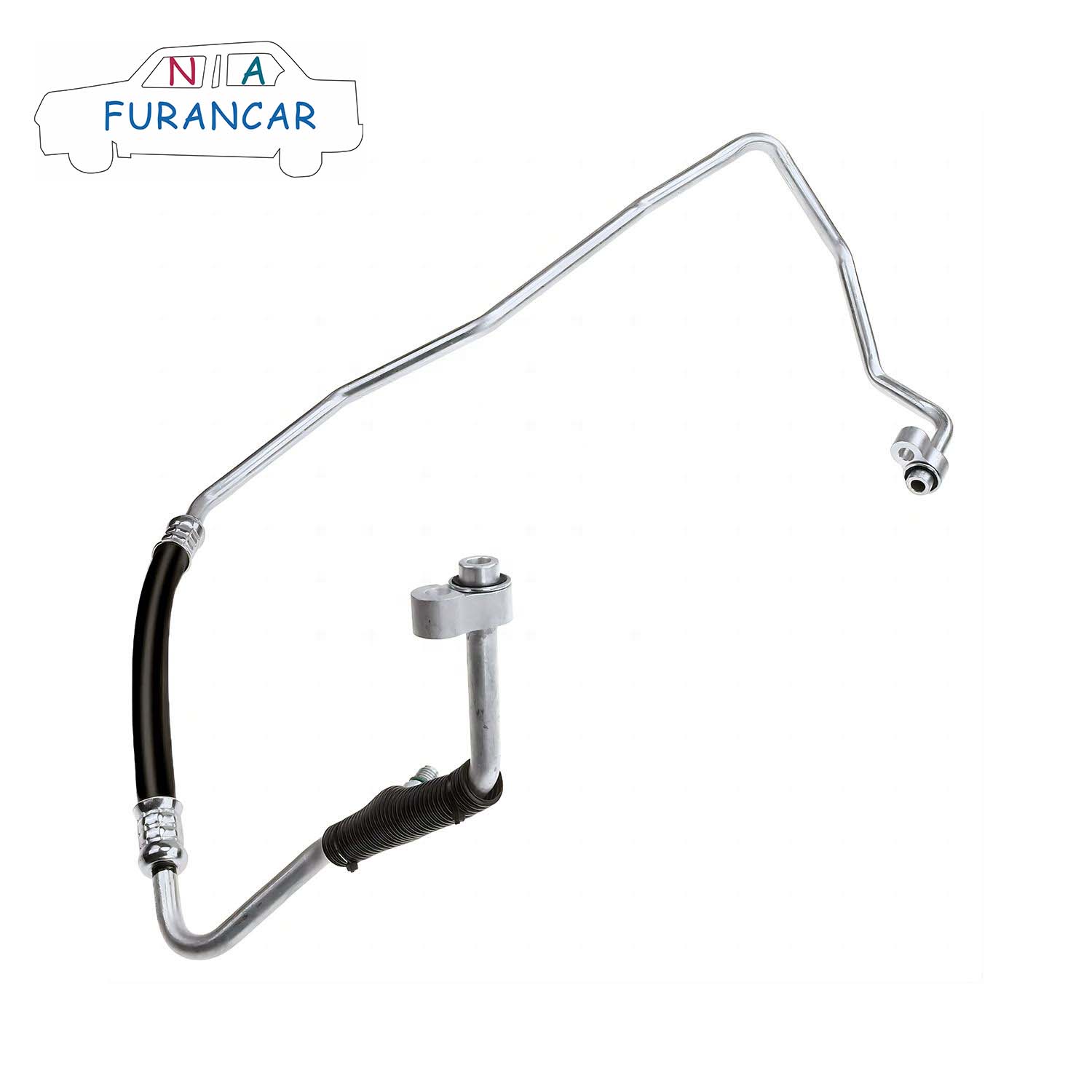
Air conditioning piping connects components such as the compressor, condenser, evaporator, and expansion valve, forming a closed system through which the refrigerant circulates. A typical air conditioning system comprises three main pipes: the compressor suction pipe, the discharge pipe, and the condenser discharge pipe. Air conditioning piping may be categorised by material into copper tubing, aluminium tubing, and rubber hoses; by pressure into high-pressure lines and low-pressure lines; and by refrigerant state into gas lines and liquid lines. Automotive air conditioning piping primarily comprises aluminium tubing, fittings (clamps, connectors, nuts, etc.), air conditioning rubber hoses, air conditioning corrugated tubing, charging ports, and O-rings.


There are various types of connectors for automotive air conditioning lines, with threaded connections and clamp-on connections being two of the more common methods.

Where pipelines run parallel to one another in pairs, weld nut holes shall be designed at suitable positions on the front enclosure outer panel. Pipelines shall be secured using multiple pipe clamps, with fixed mounting points spaced at 300mm intervals. Figure 3 illustrates a high-low pressure pipe assembly employing dual pipe clamps.


The securing of the pipes requires the use of cable ties for assistance, as shown in Figure 3. Specific air conditioning drain pipes are secured to the heating water inlet and outlet pipe assemblies using cable ties, serving to anchor and stabilise the installation.


The processing workflow for piping components is as follows: Cutting to length, deburring and rounding edges, turning ends, end machining, turning grooves, chamfering and deburring, inspecting end dimensions, bending, drilling, inspecting bend dimensions, pre-weld cleaning, fitting nuts, welding pressure plate valve seats, weld inspection, post-weld cleaning, inspecting cleaning results, fitting valve cores, marking, fitting O-rings, placing in plastic bags, Hose cutting, aluminium sleeve assembly, crimping, bellows cutting, bellows fitting, aluminium sleeve assembly, crimping, airtightness inspection, overall inspection. Ensure the airtightness of processed piping meets design requirements.


Air conditioning piping must undergo the following tests and achieve satisfactory results before being put into service.

1.Leak test: Seal one end of the hose assembly, connect the other end to a quick-release sealing coupling, and charge the system with dry nitrogen at a pressure of 3–3.2 MPa via the coupling. Immerse the assembly in a water bath for 30–60 seconds. The test is considered satisfactory if no bubbles are observed.

2.High-Temperature Resistance Test: Bend the hose assembly around a mandrel with a diameter eight times the hose's nominal outer diameter. Place it in a constant-temperature chamber at (135±2)°C for 168 hours. Remove the sample, cool to room temperature, release the hose, and meticulously inspect the outer surface for visible defects such as cracks. Subsequently, pressurise the hose assembly to 2.4 MPa and maintain for 5 minutes. Check for leakage; absence of leakage constitutes a pass.

3.Pull-off Test: Take two hose assemblies with exposed hose lengths of no less than 300 mm. Secure both ends to a tensile testing machine and apply tensile force at a rate of (25±2) mm/min until the specified minimum pull-off force is reached or the hose is pulled off to failure. The pull-off force shall meet the following requirements: - For hoses with a nominal diameter less than 10 mm: minimum pull-off force of 1,800 N - For hoses with a diameter between 10 and 12 mm: minimum pull-off force of 2,500 N - For hoses with a diameter greater than 13 mm: minimum pull-off force of 2,700 N.

4.Burst test: Mount the hose assembly on a pressure test bench. Fill the interior with coolant, expel all air, then pressurise uniformly to 12 MPa within 30–60 seconds. Observe for leakage or damage; if none occurs, the test is passed.


Can I replace sway bar links myself?

Can I replace sway bar links myself?

1. Loosen the wheel lug nuts. Loosen them slightly, but do not remove.

2. Jack up/lift the car. You will need to jack the car by placing the jack under the suspension arm so it compresses the suspension and relieves the tension on the link. (See your manual for proper jacking procedures and safety)
3. Remove the lug nuts and the wheel.
4. Identify the bad link.
5. Remove the nut holding the sway bar link to the sway bar. You will have to grip the shaft below the sway bar so it does not turn - for example pair of vice grip locking pliers. The bottom bolt you can use a socket wrench on the nut, and a wrench on the nut on the other side of the mounting point
6. Install the new link. Simple insert the lower part first, then the upper. Be sure it is installed the same as the original - the bushings are touching the sway bar - from the top: nut, metal washer, bushing, sway bar, bushing, metal washer. The lower link is simply nut, mounting point, smaller nut.
7. Tighten the nuts. When tightening the nuts, again you will need to use a socket wrench on the bottom on the larger nut, regular wrench on the smaller nut. Be sure to use the correct sizes so they do not strip/become damaged. On the top, a socket wrench and vice grips so the shaft does not spin
8. Compress the bushings about half. The bottom part should be tightened so the two nuts are against both sides of the mounting point so it has no free-play.
9. Replace the wheel and lug nut. Do this after everything is tightened on the link, make sure you have all your tools.
10. Finished.

Common Fault Symptoms, Causes and Troubleshooting Methods for Power Steering Systems

1. Power steering feels heavy or lacks assistance


Fault Symptom:


The steering becomes heavy, with a brief loss of hydraulic assistance.


Cause of malfunction:


① Oil pump V-belt slack

② Oil reservoir level too low

③ Insufficient oil pump pressure

④ Pressure control sticking

⑤ Excessive external leakage

⑥ Excessive internal leakage

⑦ Steering shaft bushing too tight

⑧ Front suspension deformation

⑨ Air present in hydraulic system


Exclusion method:


① Inspect the condition of the steering pump drive assembly. Manually depress the drive belt of the steering pump; excessive deflection indicates the belt is excessively tight and requires adjustment. Start the engine and allow it to idle. Abruptly increase engine speed to check for belt slippage. Any slippage indicates the drive belt is either too loose or excessively worn, necessitating adjustment or replacement.


② Check the fluid level in the reservoir. Should the level be below the lower mark or ‘MIN’ line, insufficient fluid is present and should be topped up to the specified level.


③ Inspect the reservoir's filter. Remove the filter and examine the screen. If excessively dirty, the filter is clogged and requires cleaning; if cracked, it must be replaced.


④ Check for air ingress in the system. First, start the engine and allow it to idle. Then turn the steering wheel several times in both directions. Observe the condition of the steering fluid. If foam is present or the fluid appears cloudy, this indicates air has entered the steering system and must be purged. Inspect the steering pump's inlet hose for cracks. If cracked, replace it. Inspect all pipe connections for looseness; tighten any loose fittings. Examine the seal ring on the steering pump shaft for damage; replace with a new part if oil leakage is detected.


⑤ Check the steering system's oil pressure. Connect a pressure gauge between the steering pump and power steering unit. With the engine idling, close the gauge valve. If the pressure fails to reach the specified value within 10 seconds, this indicates insufficient pressure from the steering pump. The pump should be disassembled for inspection and repair. Turn the steering wheel to its left or right limit position, then open the gauge valve. If the pressure fails to reach the required value, this indicates a fault with the power steering unit or improper valve adjustment. The unit should be disassembled for inspection and adjustment.


2. Power steering system is making noise


Fault Symptom:

Noise emanating from the steering pump during vehicle steering manoeuvres

Causes of Fault:

① Loose V-belt on the pump
② Damaged pump bearings
③ Faulty pressure plate or rotor
④ Excessive wear on pump rings
⑤ Insufficient reservoir fluid
⑥ Air ingress in hydraulic system or loose pressure hose connections
⑦ Improper pump assembly
⑧ Malfunctioning relief valve


Troubleshooting Procedure:


① Inspect the steering fluid level within the reservoir. Should the level fall below the lower mark or ‘MIN’ line, this indicates insufficient fluid and necessitates topping up to the specified position. Excessive fluid consumption suggests a significant leak, requiring investigation and rectification.


② Examine the steering pump drive assembly. Manually depress the steering pump drive belt. Excessive deflection indicates a loose belt, requiring adjustment.


③ Verify the presence of air in the steering hydraulic system. Open the reservoir cap, start the engine at idle speed, and turn the steering wheel several times. Observe for bubbles in the fluid. If bubbles are present, air has entered the system and must be purged.


④ Verify the reservoir filter screen is unobstructed and the hydraulic lines are correctly routed. Remove the reservoir filter screen; if excessively soiled, indicating poor fluid circulation, clean it. Replace any kinked or dented hydraulic lines.


⑤ Should all preceding checks prove satisfactory, disassemble and inspect the steering pump. Examine the vanes for scratches and the pump housing for damage. Replace any affected components based on the inspection findings.


3. Uneven steering effort when turning left or right


Fault Symptom:


During vehicle operation, unequal steering effort is required when turning left and right.


Causes of Fault:


① The spool (or slide valve) of the steering control valve is displaced from its neutral position, or although in neutral, the clearance between it and the valve body shoulder is inconsistent;

② Contaminants within the control valve cause obstruction, resulting in differing rotational resistance when turning left or right;

③ Air ingress into one oil chamber of the power cylinder within the hydraulic system;

④ Oil leakage in the circuit.


Troubleshooting Methods:


This fault is often caused by contaminated hydraulic fluid. Replace the fluid with fresh oil as specified before further inspection.


① If the oil quality is satisfactory or the fault persists after replacement, bleed the hydraulic system and inspect for oil leaks. Replace components at any leakage points.


② Should the fault persist, it may stem from improper centring of the control valve. For spool-type steering control valves, rectification can be performed externally on the power steering unit by adjusting the spool position within the valve body. If no improvement occurs after spool repositioning, disassemble and inspect the spool, measuring its dimensions. Replace the spool if significant deviations are found. For rotary-type steering control valves, fault diagnosis necessitates complete disassembly and inspection.


Common Shock /struts Absorber Questions(3)

Common Shock /struts Absorber Questions

12. Why do I need to replace worn shocks or struts?


In a nutshell: To keep the vehicle’s stability within its designed capability. Stability means keeping the body as level as possible during bumps, turns and stops, while keeping the tyres on the road under all conditions. The shock’s main function is to resist body & tyre movement, but as shocks wear the vehicle becomes unstable; the steering feels less responsive, the body leans more and the tyres grip less. Stopping ability can be reduced as much as 23% and the driver needs more skill to keep the vehicle on the intended path and from losing control on curves. Shocks cycle about 1000 times per Km driven. After 80,000 Km, that’s 80 million cycles.Because shocks use metal discs that flex with each movement, they become fatigued over time which causes the reduced performance, which is why replacement shocks and struts are suggested after 80,000 kilometres.


13. What is the difference between shock absorbers and struts?


The function is essentially the same, but the largest difference is the way they mount to the vehicle. The strut design acts an integral part of the suspension by replacing the upper control arm and acting as a pivot point for the steering. The shock design is used in addition to the suspension and steering components.


14. Do the strut mounts come with the bearings?

Many do, but only when the strut mount is also the steering pivot. The bearing is a wear item and affects the steering response as well as wheel alignment.


15. Why should replacement spring always be fitted in axle pairs?

Although one spring may have broken and requires replacing, the other springs will be fatigued, and failure may be imminent. As with shock absorbers, replacing just one spring will result in an unbalanced axle which will manifest itself with uneven braking and handling.


16. Why do I need to check suspension geometry after fitting new springs?

As springs fatigue and sag, caster, camber, toe and the turning circle are affected, therefore, a full geometry check after fitting new springs will reduce wear in tyres, track rod ends etc.


17. Why are coil springs which come off a vehicle often longer than the new springs supplied as replacements?

Because the old springs have become coil bound. They have stopped returning to their original height following extensive compression.

Does the Shock absorber need to be replaced with both?

Does the Shock absorber need to be replaced with both? Does Shock absorber damage require immediate replacement?  

The Shock Absorber tends to age and harden over time, leading to damage. The average car has two Shock absorbers. Do you need to replace both of them if one breaks? In fact, only one Shock absorber is damaged and can be replaced separately, but it is better to replace both when replacing them. That’s because while the Shock absorber isn’t damaged, it can wear and tear over time. Changing just one Shock absorber can lead to uneven support on both sides of the Shock absorber, affecting its original performance.

If the shock absorber is broken, do you need to replace it immediately?

First, when the Shock absorber is damaged, the Shock absorber will make a strange noise when it is working, and the car’s direction may be slightly deflected, making it difficult and ineffective to return to normal. At the same time, the Shock absorber loses its basic cushioning effect, transferring the absorbed Shock and Shock from the frame to the driver’s cab as it works, and the steering wheel makes a noticeable noise when it is moved. All told, the impact of Shock absorber damage is significant and should be replaced in a timely manner.

How does a sway bar differ from a sway link?

How does a sway bar differ from a sway bar link ?

Sway bars and links are found in ATVs, forklifts, racing cars and family cars – basically any type of vehicle with a suspension.


Maintaining a vehicle in an upright position during a turn is vital to safety. The parts within a suspension system that help to control this movement are the sway bars and sway links. A sway bar is a long steel tube or bar that runs across the front and back of a vehicle. The bar allows the suspension to flex depending on the angle of the turn forcing one side of the vehicle to raise or lower to offset the turn on the opposite side.

A sway link, sometimes referred to as a dog bone, connects the sway bar to the a-arms in the front of a vehicle and in the back suspension. Generally, there are four sway links in every application – one for each wheel. These links hold the vehicle flat in a turn to prevent the vehicle from flipping over. Given their role in preventing rollovers, sway links must be precisely engineered for each application.

Knowing when to replace a sway link is just as important as its initial selection. When sway links wear, they make a clunking noise and tension loosens between the sway bar and the a-arms.

How to Make an Emergency Power Steering Hose Repair

How to Make an Emergency Power Steering Hose Repair 


Ever had a power steering hose spring a leak and you are in the middle of nowhere, there is a parts store but your part isn't available. I will show you a quick and easy way to repair a power steering hose. 
Determine leak location: You have established you do have a power steering hose leaking, you can turn the steering wheel with the engine running and power steering fluid will spray out the hole in the hose, you may need an assistant for that part. You may also need to jack up the vehicle to see where it is leaking from. Set parking brake and use blocks or jack stands for safety after lifting vehicle. You may have to add fluid to an empty power steering pump to locate the leak. 
Cut the hose: After you have determined where the leak is, then remove the bad spot in the hose.   
Install the hose clamps: Install the hose clamps 2 on each side, Stagger hose clips against each other. This allows you to get them closer together and have more clamping force on the splice. Slide in the brass coupling, install the hose clamps on the other end of the hose and slide the hose into the coupling. Make sure you slide it all the way on. 
Tighten the clamps as tight as you can get them without stripping the clamps out, put the hose back into position in the vehicle. Fill the power steering tank and recheck for leaks, if you have made a successful repair the power steering will work and you won't lose a drop of fluid. 

How to repair noisy control arm bushing?

How to Repair a Noisy Control Arm Bushing If the bushing is just loose, then it is either knocked loose or installed incorrectly.
Chances are, you can save this bushing just by tightening it.
However, in most cases your bushing will wear out and you will have to replace it.
Either way, you should take your vehicle to an auto body professional who can perform this repair or replacement job for you.
It's not a good idea to ignore the jingle or knock, as this can cause a steering failure and you will no longer be able to control the direction of the vehicle.
It is best to resolve the issue as early as it is convenient for you.

Is there any danger when the balance bar ball head is broken?

Is there any danger when the balance bar ball head is broken?
If the ball head of the balance bar breaks, there will be a certain safety hazard. Because the ball head of the balance bar is broken, it will lead to the deviation of the car direction. The breaking of the ball head of the balance bar will have the following effects:
1. Different tread patterns on both sides or different tread depth and height.
2. Uneven tire pressure on both sides will make the tire different in size, which will inevitably produce deviation when rolling.
3. The front shock absorber is faulty. After the failure of the front shock absorber, when the vehicle is running, a high and a low two suspension are not evenly stressed, resulting in running deviation.
If the ball head of the balance bar breaks, the following phenomena will occur:
1. Abnormal noise will be heard from the front of the vehicle when the vehicle is traveling at low speed or the road surface is rotten.
When parking, if you step on the brake slightly, there will be a “click”.
3. When auto starts, the front wheels of the car will make a clunking sound as it accelerates.
There are several ways to determine whether the balance ball head is damaged:
1. Press the front end in place to see if there is any abnormal noise. If there is abnormal noise, there is a problem.
2. Hold the head of the balance pole and shake it to see if you can shake it. If it shakes, there’s something wrong, because it doesn’t shake properly.

Power Steering Hose Method of inspection

Power Steering Hose Method of inspection 
1. Where visible (without the removal of reservoir cap), check the power steering fluid level in the reservoir. 
2. 
Check the condition of power steering pipes and hoses. 
3. 
With the front road wheels on the ground, vehicle in neutral gear and the parking brake applied, run the engine and rock the steering wheel in both directions. 
Check: a. by feel at the steering wheel, that the system is operating b. for leaks in the system c. that feed pipes are free from damage and are not chafing on other parts of the vehicle. 
4. In the case of external power systems check: a. the ram anchorages for cracks, damage and security to the frame or other fixed members of the vehicle b. the ram for cracks and/or damage c. for movement indicating wear at the anchorage point d. misalignment or fouling of components. 
5. With the engine stopped and steering wheel lightly rocked, check for excessive free play between ball-pin and valve. 
Where practicable, check the security of the power steering pump and the condition of its drive system. 
7. 
Check for any inappropriate repair or modification to power steering system components.